
|
TinySA4 /
Fault Finding for the tinySA Ultra / Ultra+This page describes how to find what is wrong with your tinySA Ultra for the most common problems. Black screen after firmware update You either loaded an incorrect firmware or the loading did not complete. See the firmware updating guide for how to retry loading a firmware. UI hanging or no data shown If the screen shows the user interface but no scan and/or is not reactive to touch there may be a problem with the LCD touch.
Self test fails The built-in self test does all these tests but doing them manually can give a quick indication of what component(s) to replace.  If the yellow line at the left is absent or goes up only a bit, as can be seen in below picture, either the mixer or the LO is bad. There is no easy repair for this but luckily this problem is very rare. 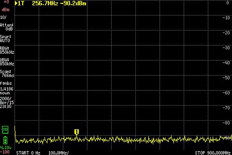 Next step is to connect RF and CAL connectors using a short SMA cable and enable MODE/CALIBRATION OUTPUT/30 MHz and go back to spectrum analyzer mode.  A first indication something is wrong is when the indicated level deviates more then 4 dB from -35dBm like seen in picture below. If the difference is 5dB or more, the input switch (U22) needs to be replaced. 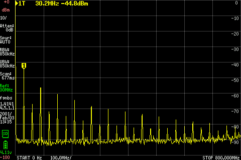 Now activate the LNA using LEVEL/LNA. The noise floor should drop about 20 dB and the indicated level may change up to 6 dB  If the signal drops much more then 6 dB, or disappears completely, the LNA needs to be replaced. If all above tests are OK, switch off the LNA and set the internal attenuation to 2, 4, 8 and 16 dB (see picture below). With different settings of the attenuation the noise floor should go up but the level indicated by the marker should stay the same within +/- 1 dB If the measured level with changes of the attenuation changes more then 2 dB the attenuator should be replaced 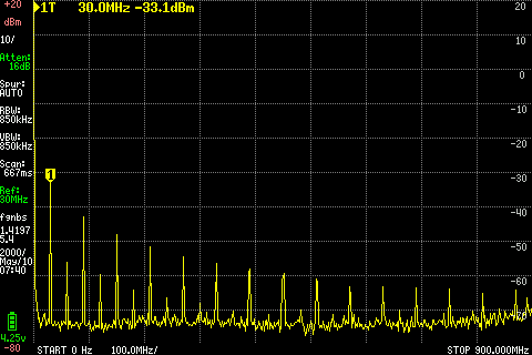 These are the components that may have to be replaced:
All these components are located under the removable shield next to the RF connector. Power down the tinySA before removing the shield. Fault finding with oscilloscope When you do have a oscilloscope you can trace the output signal in generator mode from the mixer to the RF connector and check the levels. With the generator set to 10 MHz and maximum output power you should see about 180 mVpp on the following components.
Using an oscilloscope and the CAL output at 30 MHz you can trace the input signal from the RF connector into the mixer by probing at these locations. WARNING: The level is rather low, about 10 mVpp LNA not active:
LNA active:
|